 |
| October 21, 2014 | Volume 10 Issue 39 |
Designfax weekly eMagazine

Archives
Partners
Manufacturing Center
Product Spotlight
Modern Applications News
Metalworking Ideas For
Today's Job Shops
Tooling and Production
Strategies for large
metalworking plants
Basics of motion control:
How feedback encoder devices operate
By MICROMO micro motion solutions
Feedback is used in closed-loop systems in applications all over the world to control speed and/or position, and it has an important role in keeping equipment operating smoothly and accurately. Feedback is available in a variety of devices as well as models. It is important to understand how feedback operates, so the best benefits can be used in the application.
Open loop vs. closed loop
Many applications operate open loop and many operate closed loop. In an open-loop system, the operation can become uncontrolled; in a closed-loop system the process is controlled. The difference is feedback.
An open-loop system is a process in which the signal travels from the control to the motor. An example of an open-loop system is as follows: a motor is used in a bin-sorting application, and everything proceeds as expected as long as the motor can pick and place parts in the proper bin. However, if for some reason the mechanism jams and the motor can't move, the control is not aware of the situation and will continue sending commands that are essentially ignored, so the parts do not get sorted.
In a closed-loop system, the signal travels from the control to the motor, as above. However, the difference is that there is another signal, a feedback signal, that returns to the control, thus informing the control if the operation was completed successfully. If the feedback informs the control that the operation was not successful, then the control could alert an operator that the process was not completed correctly. Closed-loop systems use feedback for speed/position information and process control in many applications.
There are a variety of devices available in the marketplaces that are employed to derive information about the application's speed and/or position, thus controlling and guaranteeing that the process occurs correctly. These include: tachometer, Hall sensors, encoder, and resolver.
Tachometer
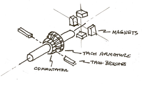
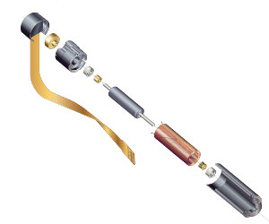
Figure 1.
Tachometers are rotating electromagnetic devices typically connected to a motor shaft, and when the tachometer shaft is rotated, it outputs a signal (i.e., it outputs a voltage). The faster the tach shaft is turned, the larger the magnitude of voltage developed (i.e., the output signal is directly proportional to speed). This output voltage also provides a polarity (+ or -) that indicates direction of rotation (CW or CCW). A basic tachometer assembly is illustrated in figure 1 and consists of a tach rotor, magnets, and brushes.
Analog, or DC tachometers as they are often termed, play an important role because of their ability to provide speed and direction information. This information can be fed to a meter (for visual speed readings) or used in servo control for stabilization purposes. The DC tach provides the simplest, most direct method of acquiring this information.
As an example of utilizing a tach for velocity information, consider a conveyor that must move loads at a constant speed. The motor is required to rotate at 3,600 rpm. With a tachometer voltage constant of 2.5 volts/Krpm, the voltage read on the tach terminals should be:
3.600 Krpm x 2.5 volts/Krpm = 9 volts
If the voltage is indeed 9 volts, then the motor is rotating at the correct speed. The control will monitor this voltage, assuring desired speed is maintained.
Hall sensors
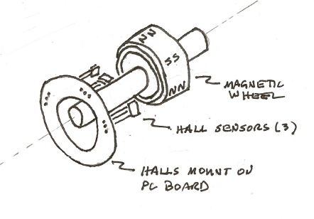
Figure 2.
Hall sensors are solid-state devices that are used to sense or detect magnetic fields. As a magnet passes by the Hall sensor, the sensor's output changes from "on" to "off" -- it's a digital signal and the output is either "high" or "low."
The basic Hall assembly illustrated in figure 2 consists of three Hall sensors (placed 60 mechanical degrees apart), a magnet "wheel" (attached to the motor shaft) and parts to hold the sensors in place. In some motors, the design is arranged so the Halls sense or detect the motor magnets, thus eliminating the magnet wheel.
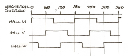
Figure 3.
As the shaft rotates, the magnet "wheel" passes by the Hall sensors, and as illustrated in figure 3 the Hall output change state. These square wave signals provide information to the control.
Time between these pulses is used to derive data for speed control or speed regulation. This scheme works best at higher speeds. At very low speeds, the pulses are far apart, thus it becomes extremely difficult to accurately regulate speed. Note that since the position of the Halls on the motor housing are known, therefore the rotor position is known.
As an example of using Hall sensors, consider a brushless motor application. Hall sensors used for "electronic commutation" are turning "on" and "off" as a magnetic field passes by, providing information about rotor position. The control uses this information to turn "on" specific power devices, applying power to specific stator windings. This maintains the relationship between the rotor permanent magnet field and the stator winding field at the proper angle for rotation.
Encoder
An encoder may be termed a rotary encoder, digital encoder, optical encoder, digital tachometer, or incremental encoder. It's simply a mechanical-to-electrical conversion device, turning mechanical motion into velocity or position information for motion control systems.
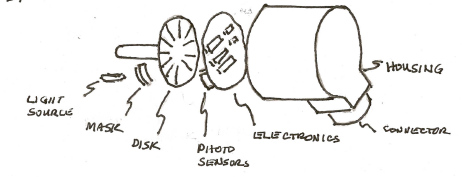
Figure 4.
A basic encoder (illustrated in figure 4) consists of a light source, a mask, a coded disk (with opaque lines), photo sensors (also termed photo array), and electronics. The path of light is through the mask, through the coded disk, and is detected by the photo sensors. As the encoder's shaft is rotated, the light is alternately passed through or blocked, thus an alternate light and dark pattern is detected by the sensors. The electronics convert this into an electrical signal representing square waves (light "passing through" or "blocked" converts to "high" or "low" pattern). Note, this example explanation uses a light source to explain how an encoder works. However, there are other technologies available such as magnetic.
The number of lines etched on the coded disk is dependent on the resolution desired for the application: increasing resolution increases accuracy in the application. If the disk has 1,000 lines, there would be 1,000 "high"/"low" cycles or 1,000 pulses per revolution (ppr). By counting the number of pulses, the position of the shaft relative to its starting position is known. Adding another measured value (i.e., time) to the information, it is possible to determine velocity.
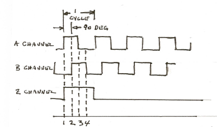
Figure 5.
Another pattern of lines is added to the coded disk, and these two lines are usually termed "A channel" and "B channel." They are arranged with an offset of 1/2 cycle (I.e., quadrature) as illustrated in figure 5. When the encoder reverses direction, then channel B goes high before channel A. Using this relationship, it's possible to determine direction of rotation. Sometimes a third channel is added. This channel has one pulse per revolution and is typically referred to as an "index" or "home" pulse (Z channel). Additionally, some encoder models include a channel that simulates Hall sensors.
Controls will read positive and negative transitions of the encoder pulses, resulting in the number of pulses/revolution (ppr) being multiplied by 4 times -- thus the counts per revolution (cpr) for a 1,000 ppr encoder will be 4,000 cpr. This is the resolution of the encoder, which is used to determine accuracy.
Encoders are classified into two basic types: incremental and absolute. The discussion above covered an incremental encoder. The absolute encoder provides a "specific address" or "whole word" for each shaft position throughout 360 degrees. This code is derived from independent multiple tracks on the disc.
Absolute encoders can provide different types of output. The most common are parallel absolute output and serial synchronous interface (SSI). For parallel output, each bit of the data word is output in parallel on a separate data line. SSI transmits encoder position information on a single pair of conductors rather than one conductor per bit. A clock pulse train from a control tells the encoder when to send out data bits.
Since position information is directly on the coded disk assembly, the disk has a built-in "memory system," and a power failure will not cause position information to be lost. Therefore, it will not be required to return to a "home" or "start" position upon re-energizing machine power.
As an example of using an encoder, consider a cut-to-length application. An encoder is connected to a measuring wheel that rests on the uncut material. As the material moves along a conveyor, the encoder outputs a series of pulses representing the distance the material has moved. The control counts these pulses, and when the appropriate number of pulses has been received, the control sends a command to a blade to cut at the measured length.
Resolver
Resolvers are similar to motors; that is, there is a rotor and stator. A reference "signal" is placed on the rotor, and as it revolves, the output of the signal changes directly proportional to the angle through which the rotor has moved.
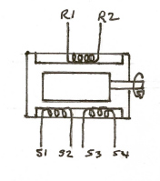
Figure 6.
A simple resolver, as illustrated in figure 6, contains a single input winding and two output windings. A reference AC "signal" is applied onto the input winding (R1-R2), which is induced onto the rotor and then passes onto the output windings (S1-S2 and S3-S4). The windings are 90 degrees apart, and the envelope of the signal provides a sine and cosine output. These signals are then fed into the control.
The magnitude of the output voltage of the sine and cosine signals is proportional to the angle the resolver rotor has moved through and thus provides position information. The leading or lagging sine/cosine relationship provides direction information.
There are various types of resolvers. The type described above would be termed a single-speed resolver; that is, the output signal goes through one sine wave as the rotor goes through 360 mechanical degrees. If the output signal went through four sine waves, as the rotor goes through 360 mechanical degrees, it would be termed a four-speed resolver.
Each feedback device has its own characteristics, parameters, operating range, and advantages. Figure 7 presents an overview of feedback devices.
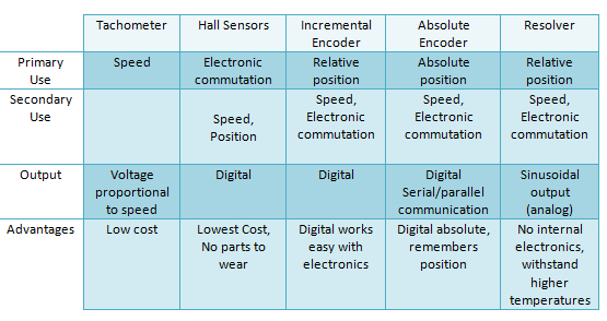
Figure 7: Overview of various feedback devices.
Each application should be reviewed to determine needs, and then the best features and advantages of the feedback device can be used in the application.
Source: MICROMO
Published October 2014
Rate this article
View our terms of use and privacy policy